
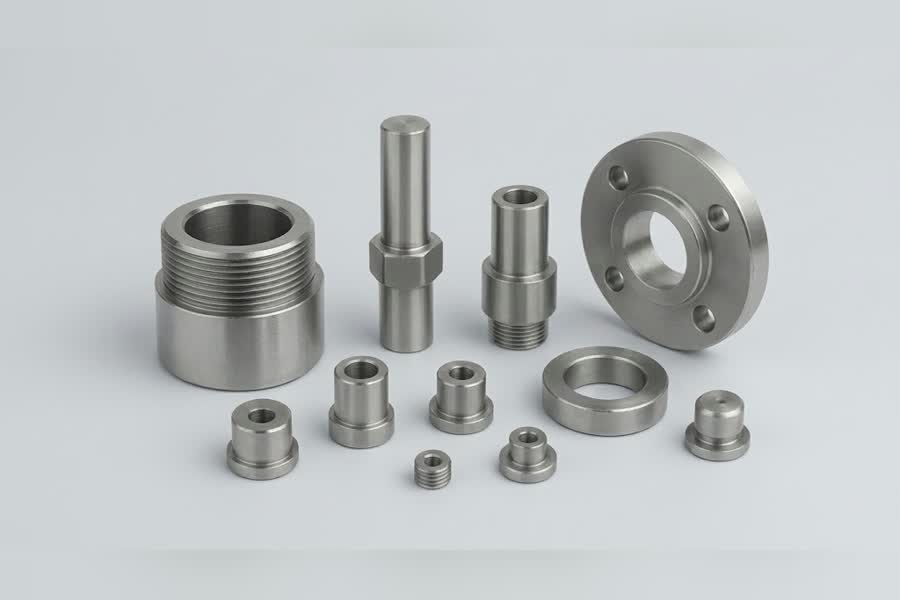
When sending a CAD file for CNC machining, it’s not just about the shape and size that are being shared. Every component has dimensional requirements that influence its functionality, assembly, and manufacturing cost. By knowing the tolerances of machining before you send your design, you can avoid production problems and extra costs. Whether it is choosing the right dimensional limits or understanding the critical features, the right tolerance planning makes sure that your digital design is translated correctly into a physical component.
1. Understanding CNC Machining Tolerances and Their Importance
CNC machining tolerances are the acceptable range of deviation of a component’s dimension from the specified dimension. Not all of the features of a product are created at exactly the same measurement in any machining process. There are small dimensional differences, caused by tool movement, cutting forces, temperature changes, and material properties.
For example, a tolerance of a 20 mm shaft is 0.05 mm, which means that a 19.95 mm and 20.05 mm shaft are both acceptable because they fall within the tolerance. However, with a tolerance of ±0.01 mm, the level of variation is much less. These limits have a direct impact on the fit-up and operation of the components. A decorative cover may be allowed to be out of alignment with the bearing housing dimensions, whereas the dimensions of a bearing housing must be exact for correct alignment. An understanding of this difference is essential in establishing reasonable manufacturing specifications.
2. Differentiate Between Standard and Tight Tolerances
Standard tolerances are used to set reasonable limits on dimensions that do not need to be extremely precise. Features with tight tolerances are those that have a small tolerance for error that will impact assembly, movement, sealing, or function. Choosing between them depends on the purpose for which the component is to be used – it is not necessarily a requirement that the highest level of precision be provided.
When it comes to on-demand CNC machining, tolerance also has an impact on the quotation, machining time, inspection requirements, and the production cost. To keep dimensional limits tighter, manufacturers may need special tooling, extra setups, or more detailed measurements. As such, the use of tight tolerances where they are needed, but not elsewhere, leads to a more cost-effective manufacturing strategy while meeting critical functional requirements.
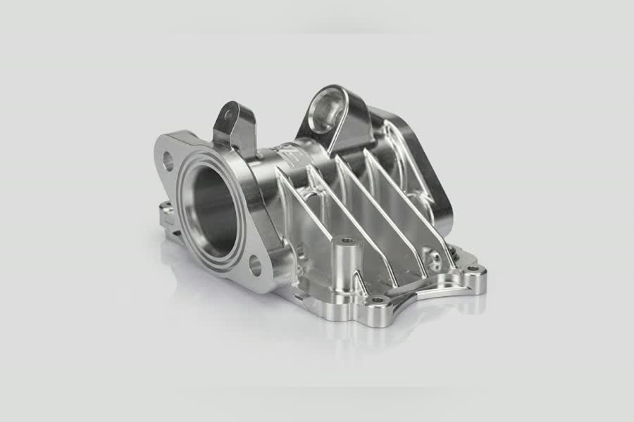
For reference, common general tolerances include:
- Standard CNC milling: Approximately ±0.13 mm under typical general machining specifications.
- Screw machining: Approximately ±0.13 mm for standard dimensional requirements.
- CNC routing: Approximately ±0.13 mm, depending on material and geometry.
- Precision machining: Tolerances around ±0.02 mm or ±0.01 mm may be achievable upon request.
These figures are not universal guarantees. Actual capabilities depend on the machine, material, dimensions, and manufacturing conditions.
3. Identify Critical Dimensions in Your CAD Design
Not all of the dimensions are equally critical for the manufacturing process. Prior to sending your CAD files, determine characteristics that directly affect the function of the parts. Typically, these consist of mating surfaces, mounting holes, bearing seats, threaded connections, alignment features, etc.
For example, a hole in a mounting plate may need to be controlled for diameter and position to fit exactly with another component. An outside decorative border, on the other hand, may not require the same degree of accuracy. Using the same tolerances throughout the design may make the manufacturing more complicated than necessary.
Analyse the assembly requirements of the component and determine dimensions that affect the moving, clearance, interference, or contact. Give suitable tolerances for these features in the technical drawing. By clearly separating the critical dimensions, the machinist will know which dimensions to focus on more when producing and checking the parts.
4. Understand How Material and Geometry Affect Accuracy
The selection of materials is important in determining the tolerances that can be achieved in the machining process. Aluminium tends to be very machineable, while stainless steel can present more problems of cutting resistance and heat. Plastics present other factors, as some materials expand or contract under the machining forces and some materials deform.
Dimensional consistency is also influenced by component geometry. Thin walls will vibrate during cutting, and deep cavities will need longer tools, which may bend. The small internal corners may require special tooling, making machining more difficult.
Consider these important design factors before submission:
- Wall thickness: Extremely thin walls can deform under cutting pressure. General guidelines suggest approximately 0.8 mm minimum for metals and 1.5 mm for plastics, depending on geometry.
- Cavity depth: Deep pockets increase tool deflection and vibration. Keeping depth around four times the width or less can improve machining stability.
- Internal fillets: Larger internal radii accommodate stronger cutting tools and simplify material removal.
- Hole dimensions: Standard drill sizes simplify machining and reduce unnecessary tooling requirements.
- Undercuts: Complex undercuts may require specialized cutters or additional machining operations.
Considering these details makes your CAD model easier to manufacture while supporting consistent dimensional results.
5. Specify Tolerances Clearly in Technical Drawings
A 3D CAD model can convey the geometry of the parts, but it cannot necessarily convey all of the manufacturing requirements. Technical drawings convey further details of dimensional tolerances, geometric tolerances, surface finish, and inspection sequence. Dimensionalize clearly and include tolerances with the appropriate features. General tolerances may be used for unspecified dimensions, and more specific tolerances for individual dimensions should be noted directly on the dimensions. In a metal context, for instance, ISO 2768-m gives general tolerance information, and ISO 2768-c is a coarser tolerance. The standard and edition applicable should be confirmed with your manufacturer, however.
Another useful method is called Geometric Dimensioning and Tolerancing (GD&T). Specifies the requirements for flatness, perpendicularity, concentricity, position, and other characteristics. These controls convey a sense of spatial relationships between features, in addition to their dimensions.
6. Consider Surface Finish and Post-Processing Requirements
The dimensional accuracy of the component is just one aspect of component quality. Surface finish can have an impact on friction, sealing, appearance, corrosion resistance, and interaction between mating components. Thus, convey finishing requirements before manufacturing is started.
The typical surface finish of a CNC-machined surface is 125 µin Ra (3.2 µm Ra) but can depend on the material, tooling, and machining conditions. Final dimensions may vary with other treatments.
For instance, anodizing coats aluminum with an oxide layer, which may impact fitted dimensions. Powder coating and electroplating also add more material thickness. Consider these changes in the final tolerances, particularly for holes, threads, and mating surfaces.
7. Prepare Your CAD Files for Manufacturing Review
Confirm that your electronic files and drawings have the same manufacturing specifications before sending your design. 3ERP is used to enable CNC milling, turning, EDM, grinding, and other processes for custom metal and plastic parts. Its engineers analyze designs submitted and look for any potential manufacturability issues.
A good submission package should contain a STEP or IGES model, and PDF or DWG drawings if detailed specifications are important. Some quoting requirements can be met with STL files, but not the same parametric information.
Ensure your package contains material specifications, critical tolerances, surface finishes, thread details, and applicable inspection requirements. 3ERP can also give feedback in the Design for Manufacturability stage before production, which aids in identifying unnecessary precision and geometry-related complications.
Conclusion
By knowing the CNC machining tolerances, you can set realistic expectations for dimensional accuracy, functionality, and manufacturing costs before sending your CAD files. The best way is to find out what features are essential, choose the appropriate materials, assess geometric constraints, and make requirements explicit.
Do not impose excessively close tolerances where normal manufacturing tolerances will do. Instead, focus on the relationship of function and use, and communicate requirements by means of detailed technical drawings. 3ERP’s precision machining, engineering support, and ISO 9001:2015-certified quality system ensure that the correct CAD designs are converted into accurately manufactured components—this careful preparation results in smoother production, fewer revisions, and more reliable results.